This is a fairly easy fitting. You have to make sure your measurements are right, and that you have confidence to drill into your engine lid.
This type of spoiler was originally available in both the UK and the USA. I bought mine from the States (DirectCarToys), so of course the following information only relates to that product, but it may well assist other installations e.g. Spoiler Depot.
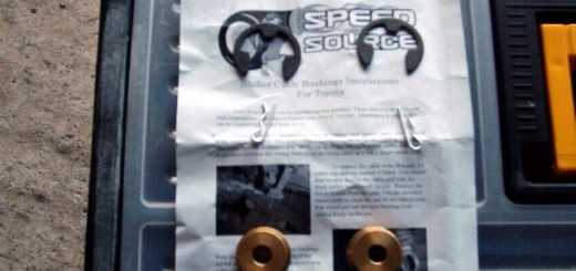
It came ready painted with a brake light, the pads for the uprights already fitted, 4 bolts and washers, 2 snap-lock wire connectors, 5 drill guides, a grommet for the brake wire and some generic instructions that had to be read very carefully to pick out what actually applied to this car.
The tools I used were an electric drill, 2mm and 6.5mm bits, stubby cross-headed (Philips) screwdriver, steel rule, long nosed pliers and a large paper clip. I also used masking tape and a 6mm circular cable connector in lieu of one of the wire connectors.
At the top of the inside of the engine lid are two large holes in the inside skin on each side, one of which is fitted with a rubber grommet. It is through these holes that you screw in the holding bolts.

Take off the grommets and prop your boot lid open so that the back of the boot lid is reasonably level. I used a small brush about 15mm long and there were some convenient holes in both the lid and metal cross-member in the engine bay to hold it firm.
The drill guides are very useful. They are strips of flat plastic about 15cms long, with a 10mm long hollow appendage in the middle. I’ve kept them for future use!
What you do is fit the little appendage on each guide into one of the 5 holes in the spoiler uprights. 2 on each side for fitting, 1 on the RHS for the brake wire. Then lightly tape them to the uprights so you can turn the spoiler over without them falling out.

Measure the centre of the top hole on the underside of the lid to the lid edge. Then measure the centre of the bolt hole in the spoiler to the end of the upright. The difference between the two is the distance of the upright from the lid edge.
Turn the spoiler over and placed it on the engine lid. If you have the lid level the spoiler won’t easily slide around. I positioned it from the front edge on both sides by the measurement calculated above making sure it was central. This I did by sight. For me the edges of the spoiler overlapped the wing / lid gap by about 2mm on each side. Repeated the position check 3 or 4 times to make sure it was absolutely right, including getting a sense that the bolt holes will align with the holes in the lid’s second skin.

In fact whilst the first bolt aligned exactly with the first hole, the second did not. It was about 3 – 5 mm to the outside from the centre, but still reasonably accessible to tighten.
When absolutely happy, I taped the drill guides to the lid. Then firmly pressing on the tape and guides with one hand, I pulled the spoiler up with the other to release it from the guides. I repeated this on the other side, and was left with the guides taped to the lid.

The instructions called for a 3/32″ drill, but I used a 2mm. Placing the bit into the guide, holding everything firmly down, applied a bit of pressure, and a 2mm hole appeared. Repeated this for the other 4 holes and undid the tape and took the guides off.

The instructions said use a 5/6″ bit to enlarge the holes. I think they probably meant 5/16″! Whatever, I used a 6.5mm having tested on a scrap piece of wood that the bolt would fit nicely into this. I put tape over the top of the small holes to avoid the bit slipping, and enlarged the holes.
The instructions did suggest you seal and paint the bare metal. This would have meant waiting 24 hours for it to dry, so I didn’t bother. I’ll let you know in a couple of years if that was the right decision!
Put the brake wire grommet into the middle hole on the RHS, then put the spoiler back on the lid, feeding the wire through the grommet. I was worried I could lose the fixing bolts down the inside of the skins, so following nelix’s (Craig’s) recommendation I fixed them to the screwdriver with blu-tack. The first ones on each side were a bit difficult because I had to do them with the lid only partly open (hence the need for a stubby screwdriver), but once these were in I could lift the lid and had more room for the second ones. With two people I could have made it easier by opening the lid further, one holding the spoiler, the other doing up the bolts.
Next came the wiring up of the brake light. I released the grommet holding the car’s middle brake light wiring at the bottom of the lid, then using the pointed pliers and a suitably bent large paper clip managed to feed the spoiler’s brake wire from the entry point at the top of the lid, from hole to hole, around to the brake light hole, pushed it through the grommet. I split the wire into its two strands, cut off about 15cms from the black wire, fitted the 6mm cable connector to it, and put it to earth by clamping it to one of the drip tray bolts that was very close by.
 jpg
jpg
It appears there are four brake light wires coming through the grommet, but only two fit into the connector which is hidden just under the heat / soundproofing, so I assume the other two terminate in the plastic sleeve. So I carefully pulled out the circular plastic press clip holding the soundproofing to gain access, and on my first try found the white and black wire would power the spoiler light. So that was the wire I used to connect the red cable to using the cable connector supplied. Who knows, the other one might work as well! Before finally fitting I trimmed it to length.

I pulled all the surplus wire back into the double skin through the grommet, replaced it and the other two at the top of the lid.
Cleaned up the swarf. Gave the spoiler a very light polish (because I didn’t know how new the paint was), followed by a light waxing, and viewed the finished result.


Very pleased.
This documentation in no way replaces the Toyota MR2 Repair Manuals. The purpose of this content is only to provide supplementary information to fellow MR2 enthusiasts. Midship Runabout and its contributing authors will not be held responsible for any injury or damages that may occur as the result of practicing any of the methods or procedures described within this website. Article and photo submissions are property of the contributing author.